Power Meter and Remote Terminal Unit Project
The Remote Terminal Unit (RTU):
A Remote Terminal Unit or RTU is microprocessor-based device which aggregates the data from various power meters in the field before sending the data through the internet to a central database for further analysis. However, the cost of commercially available RTU is above $3,000 which makes smart sub-metering projects expensive to install. SourceOne is looking into creating its own RTU system using open source microcontroller hardware such as the arduino, netduino, or raspberry pi to drastically reduce the cost of an RTU.
The idea behind the RTU is to use an arduino microcontroller to communicate with up to 16 meters in the field using the MODBUS RTU protocol through RS485 serial communications. The RS485 communication would allow the microcontroller to read metering data from meters over 300 feet away. The arduino would serve as a secondary unit, which would be controlled by primary unit such as the netduino or Raspberry Pi. The netduino would then communicate via Ethernet to a central server where the energy data would be stored and analyzed. An arduino is needed to communicate with the meters via MODBUS RTU because the netduino and raspberry pi cannot react fast enough (the timing tolerances for MODBUS RTU is at the microsecond level).
The Power Meter
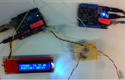
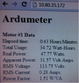
Although we have not yet built this RTU, I built a meter simulator using an arduino and netduino. The idea behind building a meter simulator is that in order to properly build the RTU, we will need multiple meters. However, commercial meters are expensive and creating a meter simulator allows flexibility. For example, the simulator can have a multiplier in the code so that even though it is actually measuring small loads, it can simulate the large loads of an industrial facility. The simulator works using an arduino which uses a current transformer (CT) sensor to measure the current and an unregulated 9V AC-AC power supply to measure the voltage (without worrying about dangerous mains voltage levels). The signals from the CT sensor and 9V power supply then go through a simple circuit to change the voltage levels into a 0 to 5 volt signal so that the signals can be interpreted by the arduino. The arduino then calculates the current, voltage, apparent power, real power, power factor, runtime, and energy usage in kWh and outputs this data to an LCD screen. The netduino primary unit then periodically asks the arduino for its data and publishes this data on the internet. The picture below shows the meter simulator running as well as the data being published on the internet.
Useful Links

